


Table of Contents
Installation and User Guide
About This Guide
This guide provides a brief introduction to the Indoor/Outdoor Plug-In Security Camera and the Tapo app, as well as regulatory information. Please note that features available in Tapo may vary by model and software version. Tapo availability may also vary by region. All images, steps, and descriptions in this guide are only examples and may not reflect your actual Tapo Camera experience.
Conventions
In this guide, the following convention is used:
| Convention | Description |
|---|---|
| Blue | Key information appears in blue, including management page text such as menus, items, buttons and so on. |
| Underline | Hyperlinks are in blue and underlined. You can click to redirect to a website. |
| Note |
Ignoring this type of note might result in a malfunction or damage to the device. |
More Info
Specifications can be found on the product page at https://www.tapo.com.
Our Technical Support and troubleshooting information can be found at https://www.tapo.com/support/.
The setup video can be found at https://www.tp-link.com/support/setup-video/#cloud-cameras.
Introduction
Your All-Weather Security Guard, Always on the Watch. From the backyard to the nursery, IP65 weatherproofing provides dependable, crystal-clear security, whether indoors or outdoors, rain or shine.
• Indoor & Outdoor 24/7 Monitoring – Place it in your living room, bedroom, baby's room, backyard, or front door for round-the-clock coverage and IP65 weatherproof construction: day, night, rain, or shine.
• 2K Color Night Vision & 2K Clarity During the Day – The camera captures low-light images in incredible 2K 3MP clarity, revealing details that the naked eye might miss with the embedded spotlights. Its superior resolution ensures that no details go undetected or blurred, far surpassing traditional Full HD 1080p.
• Secured Local & Cloud Storage‡ – Keep up to 512 GB of footage stored continuously on a microSD card† (a 32 GB card included) or choose our Tapo Care Cloud subscription service, which not only saves your 30-day video history but also provides additional benefits such as activity notifications with snapshots.
†A 32 GB microSD card is included in the packaging. Actual storage capacity depends on the size of the microSD card used.
‡Tapo Care cloud storage services require a subscription.
• Customizable Sound & Light Alarm – Record your own audio to use as an alarm and adjust the brightness of the spotlight to suit your preferences for a completely customized alarm system to deter intruders.
• IP65 Weatherproof – Helps the camera perform well even in harsh environments with rain and dust.
Appearance
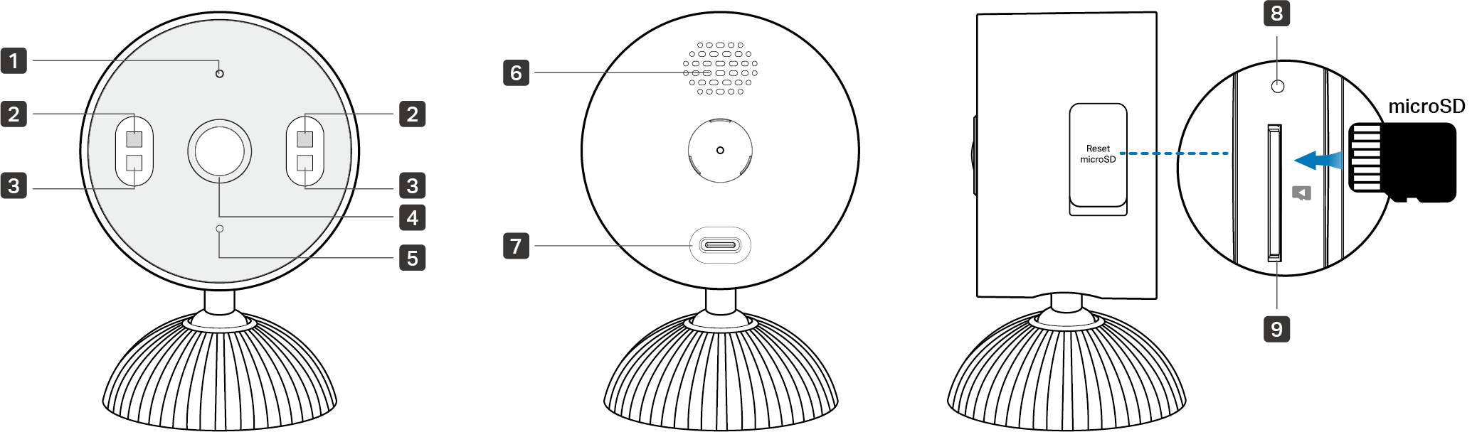
1 System LED
2 White Lights
3 IR Lights
4 Lens
5 Microphone
6 Speaker
7 USB Type-C Power Port
8 Reset Button: Open the cover and reset while the camera is powered on.
• Use a pin to press and hold for 5 seconds: Reset Wi-Fi settings
• Use a pin to press and hold for 10 seconds: Reset to factory settings
9 microSD Card Slot: Open the cover. Insert a microSD card and initialize it on the Tapo app for local recording.
System LED Indication
| LED Status | Indication |
|---|---|
| Solid red | Starting up |
| Blinking red and green | Ready for setup |
| Blinking red slowly | Connecting to Wi-Fi |
| Solid amber | Connected to Wi-Fi |
| Solid green | Connected to the cloud |
| Blinking red quickly | Camera resetting |
| Blinking green quickly | Camera updating |
Set Up Your Camera
Follow the steps below to get started with your new camera.
Step 1. Download Tapo App
Get the Tapo app from the App Store or Google Play, or by scanning the QR code below.

Step 2. Log In
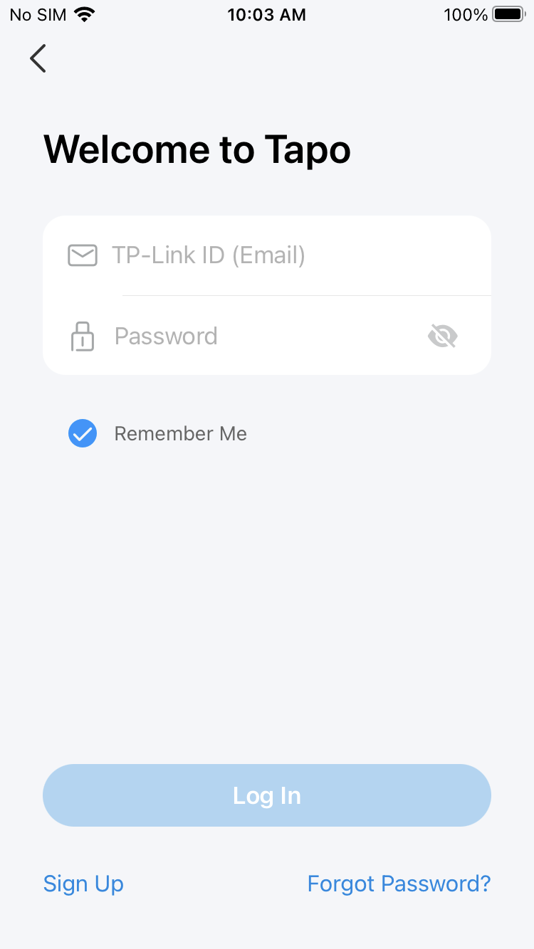
Open the app, and log in with your TP-Link ID. If you don't have an account, create one first.
Step 3. Add Your Camera
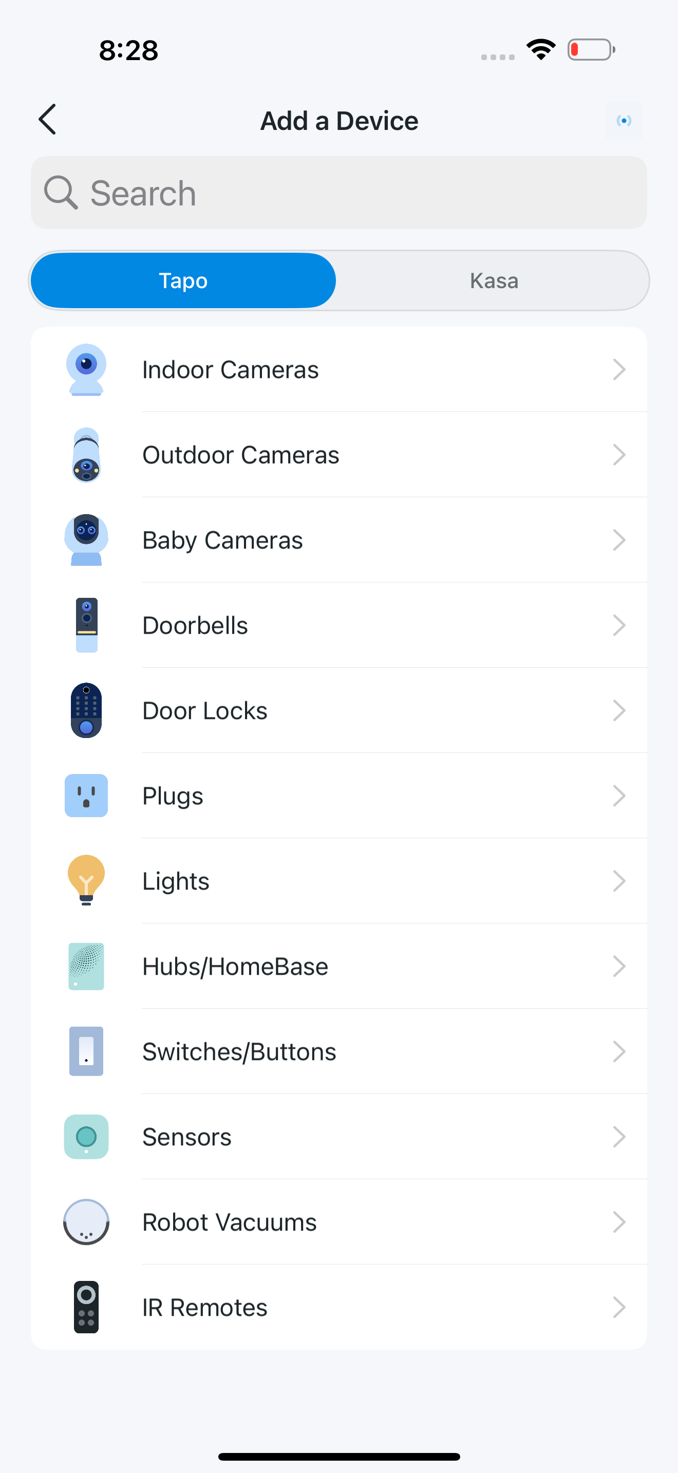
Tap the + button, choose Add Device in the app, and search for your model. Follow the app instructions to complete the setup.
Mount Your Camera
When you finish adding your camera in the Tapo app, you can set it on a table or shelf. You can also mount it on a wall or ceiling with the provided mounting template sticker, anchors, and screws. Follow the steps below to mount your new camera or follow the setup video at
https://www.tp-link.com/support/setup-video/#cloud-cameras.
Option 1: Place on a Flat Surface
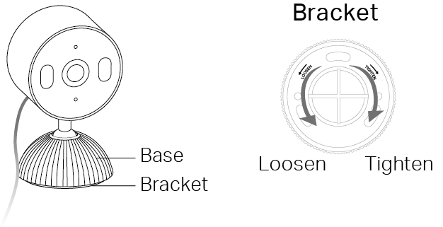
You can place the camera on a flat surface, like a table or shelf. To adjust the camera angle, loosen the bracket and adjust the shaft to your preferred angle. Tighten the bracket to secure it.
Option 2: Mount to the Ceiling
1. Drill Holes
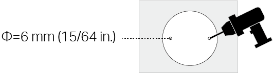
Apply the mounting template sticker to the desired mounting place. Drill two holes according to the template.
2. Unscrew the Bracket
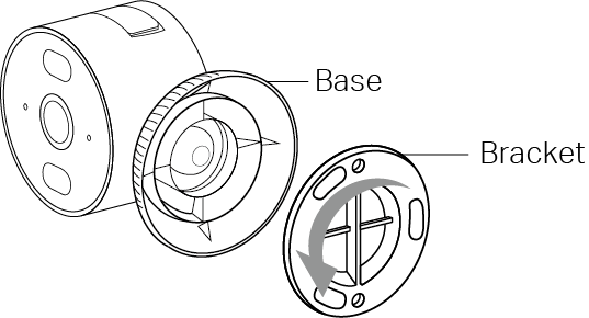
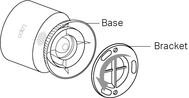
Unscrew the bracket from the base.
3. Secure the Bracket
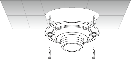
Insert two anchors into the holes and use the screws to affix the bracket over the anchors.
Mounting Screw Size:

4. Install the Camera
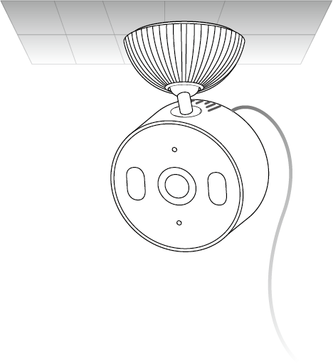
Screw the camera with the base onto the bracket. Loosen the base to adjust the angle, then tighten to secure.
5. Organize the Cable
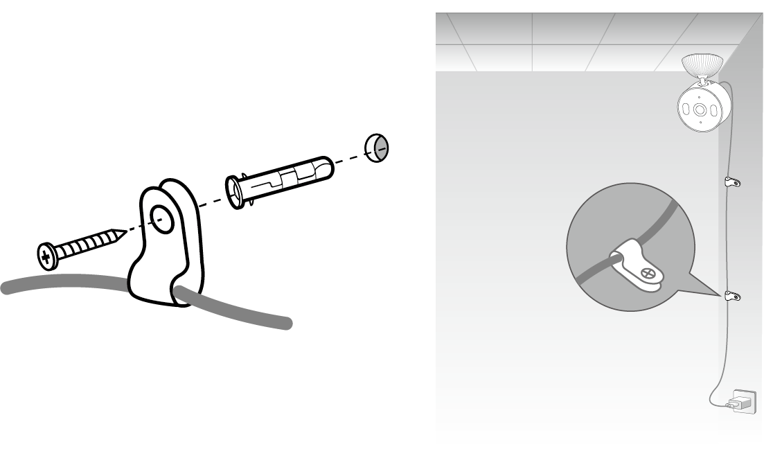
Run the cable along the wall and fix it with the provided cable clips. Here's how:
1) Drill one hole using the electric drill [6 mm (15/64 in.) Drill Bit], insert an anchor, then use a screw to affix the cable clip over the anchor.
2) Repeat the above steps to organize the cable.
Screw Size:
Option 3: Mount to the Wall
1. Remove the Camera
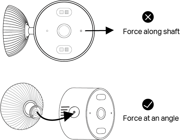
Avoid pulling the camera straight along the shaft. Instead, tilt and lift it at an angle for easier removal.
2. Install Over the Back Mounting Hole
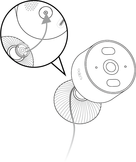
Make sure the bracket is secured to the base. Push the shaft into the back mounting hole until it clicks into place.
3. Unscrew the Bracket
Unscrew the bracket from the base.
4. Drill Holes
Apply the mounting template sticker to the desired mounting place. Drill two holes according to the template.
5. Secure the Bracket
Insert two anchors into the holes and use the screws to affix the bracket over the anchors.
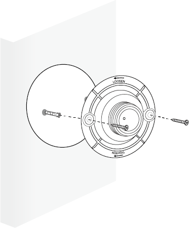
Mounting Screw Size:
6. Install the Camera
Screw the camera with the base onto the bracket. Loosen the base to adjust the angle, then tighten to secure.
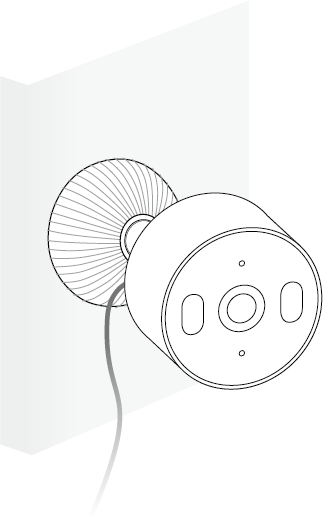
7. Organize the Cable
Run the cable along the wall and fix it with the provided cable clips. Here's how:
1) Drill one hole using the electric drill [6 mm (15/64 in.) Drill Bit], insert an anchor, then use a screw to affix the cable clip over the anchor.
2) Repeat the above steps to organize the cable.
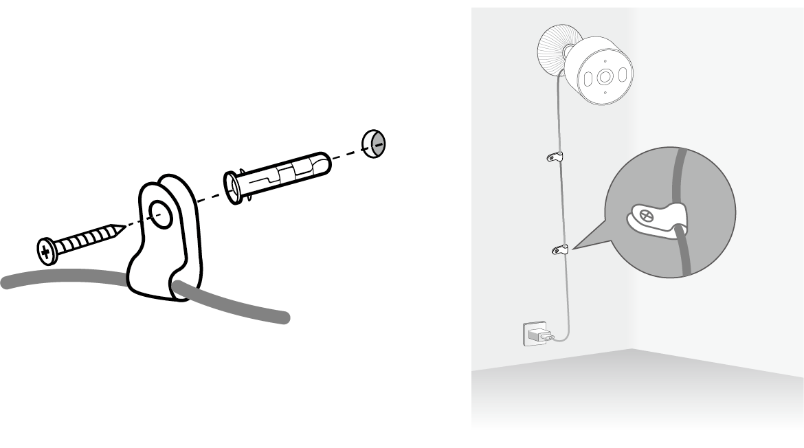
Mounting Screw Size:
Support
For technical support, the setup videos, FAQs, warranty and more, please visit https://www.tapo.com/support/
Authentication
FCC compliance information statement

Product Name: Indoor/Outdoor Plug-In Security Camera
Model Number: TCH62
| Component Name | Model |
|---|---|
| I.T.E. Power Supply | AD-D0930500100US01/A8-501000 |
Responsible Party:
TP-Link Systems Inc.
Address: 10 Mauchly, Irvine, CA 92618
Website: http://www.tp-link.com/us/
Tel: +1 626 333 0234
Fax: +1 909 527 6804
E-mail: sales.usa@tp-link.com
This equipment has been tested and found to comply with the limits for a Class B digital device, pursuant to part 15 of the FCC Rules. These limits are designed to provide reasonable protection against harmful interference in a residential installation. This equipment generates, uses and can radiate radio frequency energy and, if not installed and used in accordance with the instructions, may cause harmful interference to radio communications. However, there is no guarantee that interference will not occur in a particular installation. If this equipment does cause harmful interference to radio or television reception, which can be determined by turning the equipment off and on, the user is encouraged to try to correct the interference by one or more of the following measures:
- Reorient or relocate the receiving antenna.
- Increase the separation between the equipment and receiver.
- Connect the equipment into an outlet on a circuit different from that to which the receiver is connected.
- Consult the dealer or an experienced radio/ TV technician for help.
This device complies with part 15 of the FCC Rules. Operation is subject to the following two conditions:
1)This device may not cause harmful interference.
2)This device must accept any interference received, including interference that may cause undesired operation.
Any changes or modifications not expressly approved by the party responsible for compliance could void the user’s authority to operate the equipment.
Note: The manufacturer is not responsible for any radio or TV interference caused by unauthorized modifications to this equipment. Such modifications could void the user’s authority to operate the equipment.
FCC RF Radiation Exposure Statement
This equipment complies with FCC RF radiation exposure limits set forth for an uncontrolled environment. This device and its antenna must not be co-located or operating in conjunction with any other antenna or transmitter.
"To comply with FCC RF exposure compliance requirements, this grant is applicable to only Mobile Configurations. The antennas used for this transmitter must be installed to provide a separation distance of at least 20 cm from all persons and must not be co-located or operating in conjunction with any other antenna or transmitter."
We, TP-Link Systems Inc., has determined that the equipment shown as above has been shown to comply with the applicable technical standards, FCC part 15. There is no unauthorized change is made in the equipment and the equipment is properly maintained and operated.
Issue Date: 2026-07-16
FCC compliance information statement
Product Name: I.T.E. Power Supply
Model Number: AD-D0930500100US01/A8-501000
Responsible Party:
TP-Link Systems Inc.
Address: 10 Mauchly, Irvine, CA 92618
Website: http://www.tp-link.com/us/
Tel: +1 626 333 0234
Fax: +1 909 527 6804
E-mail: sales.usa@tp-link.com
This equipment has been tested and found to comply with the limits for a Class B digital device, pursuant to part 15 of the FCC Rules. These limits are designed to provide reasonable protection against harmful interference in a residential installation. This equipment generates, uses and can radiate radio frequency energy and, if not installed and used in accordance with the instructions, may cause harmful interference to radio communications. However, there is no guarantee that interference will not occur in a particular installation. If this equipment does cause harmful interference to radio or television reception, which can be determined by turning the equipment off and on, the user is encouraged to try to correct the interference by one or more of the following measures:
- Reorient or relocate the receiving antenna.
- Increase the separation between the equipment and receiver.
- Connect the equipment into an outlet on a circuit different from that to which the receiver is connected.
- Consult the dealer or an experienced radio/ TV technician for help.
This device complies with part 15 of the FCC Rules. Operation is subject to the following two conditions:
1) This device may not cause harmful interference.
2) This device must accept any interference received, including interference that may cause undesired operation.
Any changes or modifications not expressly approved by the party responsible for compliance could void the user’s authority to operate the equipment.
Issue Date: 2026-07-16
Safety Information
• Do not use damaged power supplies or USB cable.
• Use only power supplies listed in the user instructions. Refer to the User Manual on the product support page. Do not use any other power supplies than those recommended.
• Do not use the device where wireless devices are not allowed.
• Adapter shall be easily accessible.
• Keep the device away from fire or hot environments. DO NOT immerse in water or any other liquid.
• Do not disassemble, repair or modify the product.
• Do not use the product if the casing has been broken. Danger of electric shock.
• Never touch the product with wet hands.
• Do not place near automatically controlled devices such as fire alarms. Radio waves emitted from this product may cause such devices to malfunction resulting in an accident.
• This product is not intended to be used when providing medical care. Consult the manufacturer of any personal medical devices, such as pacemakers or hearing aids to determine if they are adequately shielded from external RF (radio frequency) energy.
• Do not use this product in health care facilities. Hospitals or health care facilities may be using equipment that could be sensitive to external RF energy.
• This product may interfere with other electronic products such as TV, radios, personal computers, phones or other wireless devices.
• Observe restrictions on using wireless products in fuel depots, chemical plants or when blasting operations are in progress.
• Do not use liquid to clean the product. Only use a dry cloth.
• Never put metal objects inside the product. If a metal object enters the product turn off the circuit breaker and contact an authorised electrician.
• Do not place heavy objects on top of the product.
• When you leave the product unused for a long time unplug the product from the power outlet.
• Adapter should be used indoors where the ambient temperature is lower than or equal to 40 ºC (104 °F).
• Operating Temperature: -20 ºC ~ 45 ºC (-4 °F ~ 113 °F)
• The camera shall be installed no higher than 2 meters (6.56 feet).
Please read and follow the above safety information when operating the device. We cannot guarantee that no accidents or damage will occur due to improper use of the device. Please use this product with care and operate at your own risk.
This product uses radios and other components that emit electromagnetic fields. Electromagnetic fields and magnets may interfere with pacemakers and other implanted medical devices. Always keep the product and its power adapter more than 15 cm (6 inches) away from any pacemakers or other implanted medical devices. If you suspect your product is interfering with your pacemaker or any other implanted medical device, turn off your product and consult your physician for information specific to your medical device.
Explanation of the symbols on the product label
Note: The product label is on the back of the product and its power supply. Symbols may vary from products.
| Symbol 符號解釋 |
Explanation 解釋 |
|---|---|
 |
Class II equipment Class II 設備 |
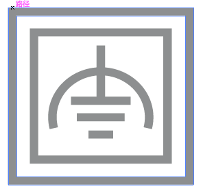 |
Class II equipment with functional earthing 具有功能接地的Class II 設備 |
 |
Alternating current 交流電 |
 |
DC voltage 直流電壓 |
 |
Polarity of output terminals 輸出端子極性 |
 |
Indoor use only 僅限室內使用 |
 |
Dangerous voltage 危險電壓 |
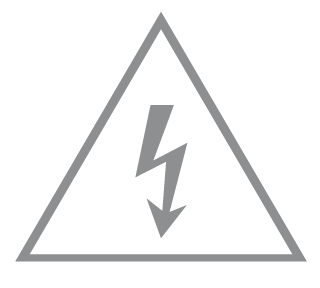 |
Caution, risk of electric shock 注意,有觸電危險 |
 |
Energy efficiency Marking 能源效率標示 |
 |
Protective earth 保護地線 |
 |
Earth 地線 |
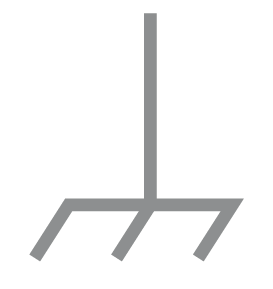 |
Frame or chassis 機架接地 |
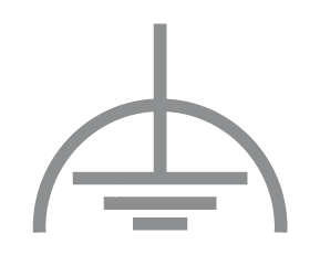 |
Functional earthing 功能地線 |
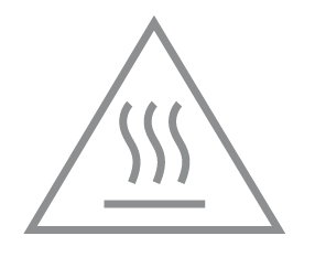 |
Caution, hot surface 警告,表面高溫 |
 |
Caution 警告 |
 |
Operator’s manual 操作手冊 |
 |
Stand-by 待機 |
 |
“ON”/”OFF” (push-push) 「開」/「關」 ( 按壓式) |
 |
Fuse 保險絲 |
 |
Fuse is used in neutral N 保險絲用於中性線N |
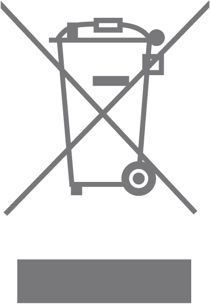 |
RECYCLING This product bears the selective sorting symbol for Waste electrical and electronic equipment (WEEE). This means that this product must be handled pursuant to European directive 2012/19/EU in order to be recycled or dismantled to minimize its impact on the environment. User has the choice to give his product to a competent recycling organization or to the retailer when he buys a new electrical or electronic equipment. 回收利用 本產品標示有「廢棄電氣電子設備(WEEE)」的分類回收標誌。這表示本產品必須依據歐盟指令 2012/19/EU 進行妥善回收或拆 解,以減少對環境的影響。 使用者可選擇將本產品交給合格的回收機構,或在購買新電器或電子設備時,交回給零售商進行回收處理。 |
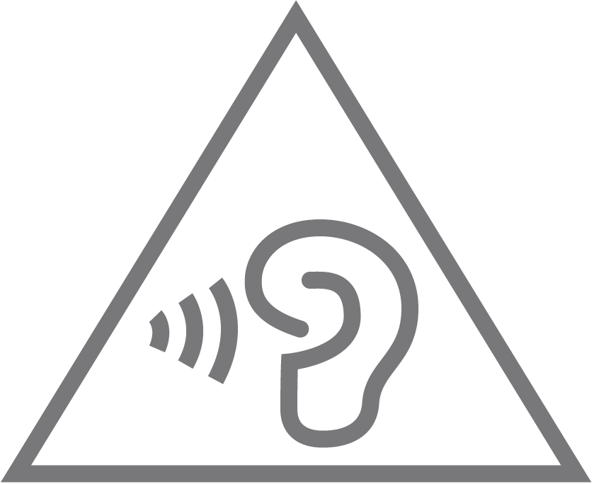 |
Caution, avoid listening at high volume levels for long periods 注意,避免長時間以高音量收聽 |
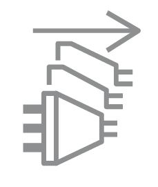 |
Disconnection, all power plugs 斷開所有電源插頭 |